This is a cool little project. I often prototype circuits on solderless breadboards. I've mostly switched to using 0805 SMD resistors and capacitors. I have a box of 1/4W 1% and a box of 1/2W 1% THT resistors but they aren't neat when they're plugged into the breadboard. I've got 0.1uF capacitors but no 1.0uF in THT.
I decided to make up these little tact switches ready to plug into the breadboard with built in hardware debounce. The debounce circuit also provides a pull-up resistor.
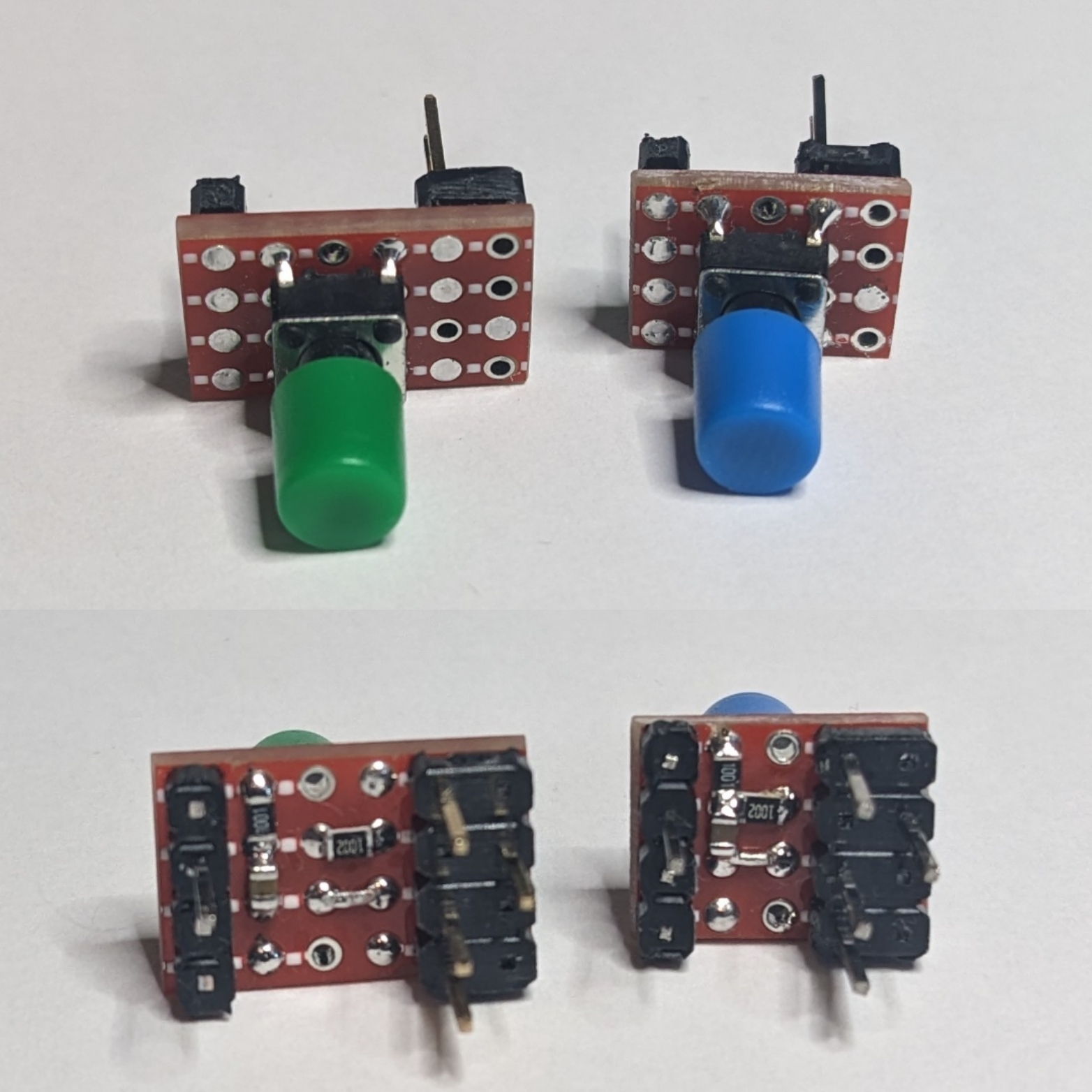
Each switch has a 10K 0805 resistor between Vcc and the MCU pin, a 1.0uF 0805 capacitor between GND and the MCU pin, and a 1K resistor between the switch and the MCU pin. The end result is a nicely debounced going low switch with a built in pull-up. They work great and I can just grab one when I need one and plug it in. I've made versions that will plug into one side or the other of the breadboard so that I can have a switch on either side depending on what works best.
The row with 3 pins is GND and the adjacent row with 1 pin is Vcc. The single pin at the other end is the debounced switched output to the MCU pin.
If anyone's interested I can post pictures of the process of making these and how I wire them up so that the work correctly.
I have no idea what this is, but it's cool shit! 🤘
Thanks! When you press a switch like this to a human it just seems like the switch turns on but if you look at the switched signal at electronic speed it will often sort of connect then disconnect then connect a bit more then disconnect again as the contacts get very close to each other. It looks like this on an oscilloscope. The MCU may interpret that as multiple fast button presses causing your circuit to behave in ways you didn't intend. A switch debouncer smooths out that bounce so that you get one, slower switch action but it's just one.
So...a debouncer just cleans up the signal from the switch.